


 he magnetic field of an MR system can be generated by different magnet systems: permanent, resistive, and superconductive. They have different distinctive features and are employed in different ways. A fourth, hybrid, magnet type is a blend of permanent and resistive magnets.
Certain alloys possess ferromagnetic properties. A magnet built of such materials has the advantage of needing no power to maintain the field strength. It needs no cooling because there is no power dissipation and it has a small fringe (stray) field when compared to the other magnet systems. Capital and operational costs of permanent magnets are low.
The disadvantages are the weight of these systems for whole body imaging, although new alloys developed during recent years have cut down the weight of permanent systems from 100 to less than 20 tons. Another drawback of permanent magnet systems are the field-strength limitations that presently seem to be about 0.3 T for magnetic resonance imaging. Most of them operate at about 0.2 T.
Many permanent magnets have a vertical magnetic field which distinguishes them from some resistive and most superconducting systems with horizontal fields (Figure 03-05). The field direction has an impact on the use of certain transmitter and receiver coils.
Such magnet systems can be designed in different ways, from a Greek temple shape to a C-shaped open system. In this case the field is produced by magnetized ceramic bricks; the outside consists of iron that provides structural support to the system, contains the stray field, and thus intensifies magnetic field strength. The field strength of permanent magnets can be influenced by the surrounding temperature, therefore temperature-stabilizing air conditioning is necessary for the magnet room.
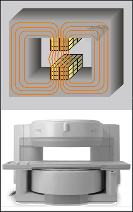
Figure 03-05:
Top: Schematic drawings of a permanent magnet. Bottom: Commercial version of a low field permanent MR imaging equipment.
Resistive (electromagnetic) systems consist basically of a suitable coil or collection of coils through which a strong electric current is passed. If these coils are set up in a proper geometry, a homogeneous magnetic field can be created, as shown in Figure 03-01 and Figure 03-06.
Such systems have a high power consumption (e.g., a 0.1 T unit requires about 20 kW), create a lot of heat, and therefore need large capacity cooling systems.
The practical upper limit for large-bore magnets is about 0.7 T, but usually 0.3 T is considered the upper limit for commercially available machines. Fringe fields are present around such systems (see Figure 18-04). The weight of these systems is typically below 5 tons. They are the lightest of all MR imaging systems. Resistive magnets have the advantage that they can be switched off when the system is not being used or during emergencies.
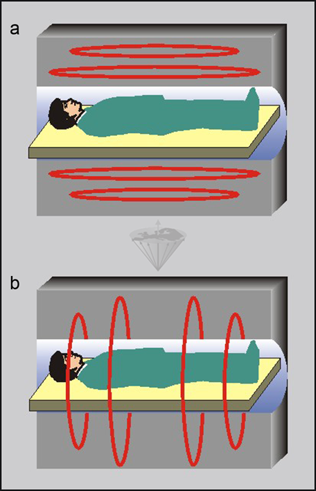
Figure 03-06:
Cuts through two different kinds of air core electromagnets. The common four loops of wire creating the static magnetic field can be arranged (a) parallel or (b) perpendicular to the patient table; the perpendicular (head to foot) orientation is more common.
Some companies have developed whole-body magnets which are hybrids between permanent and resistive systems. They are iron-cored electromagnets in which the magnetic energy of the resistive magnet is concentrated in the gap between the soft-iron pole pieces (Figure 03-07). These systems reach field strengths up to 0.4 T. Their weight is between 10 and 15 tons. Ultrahigh field research system can be hybrids between superconductive and resistive systems.
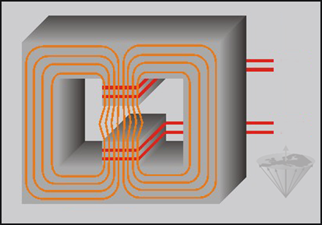
Figure 03-07:
Hybrid magnets combine permanent magnets with electromagnets. Their power consumption is high, but field strength can be increased compared to a permanent or purely resistive magnet system. These magnets are also described as ‘iron core’ electromagnets.
When certain alloys are cooled down to temperatures close to absolute zero, they show drastically reduced resistance to electric current: they become superconductive. Thus, when superconductive alloys are placed in liquid helium (at temperatures below a critical value of between -263° C and -269° C or 4 to 10 K), high currents can be driven in a coil built of that alloy, and an extremely stable magnetic field of very high field strength can be produced.
The original design for superconducting magnets involved a double cooling system using liquid nitrogen as cryogenic liquid in the first thermos container (cryostat or dewar) and liquid helium in the second inner dewar (Figure 03-08). These systems were replaced by single-dewars using a refrigerator (cryo-cooler).
When charged with current, the superconducting magnet uses virtually no electrical power, but consumes cryogenic liquids. Helium must be replenished by refilling, which is costly, or through a compressor connected to the MR system which reliquifies cryogens. Helium is a scarce and rather expensive resource. Wholesale costs of helium increased more than tenfold during the last twenty years; thus MRI running costs increased. Meanwhile, small-bore ultrahigh field animal equipment with magnets not requiring helium, but cooled solely using a standard low temperature cryo-cooler is being commercially offered; whole-body system are being developed.
Superconducting magnets have large fringe fields and are usually shielded so that the environment is protected.
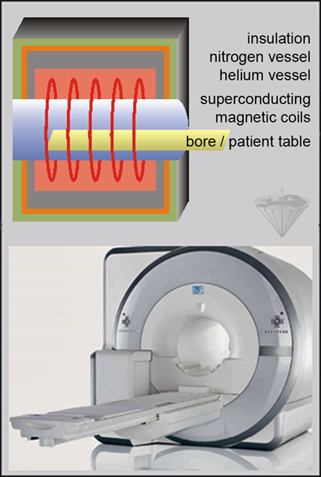
Figure 03-08:
Top: Schematic drawing of a superconductive MR imaging system.
The magnetic field is produced by electric current flowing in wire loops cooled by the surrounding liquid helium. The power supply is disconnected once the system is charged and running at the desired field strength. Recent machines do not require a nitrogen vessel any more.
Bottom: Commercial version of an ultrahigh field (3 Tesla) superconductive MR imaging equipment. A circular bore of 70 cm in diameter is minimum common standard.
The physical field-strength limitations for superconducting magnets are not yet established. For imaging purposes, small and whole-body systems up to 9.4 T have been used; scientific machines for spectroscopy and imaging are being developed for fields of up to 14.1 T — field strength is permanently pushed further up. Only superconducting magnets can be used for such purposes [⇒ Moser 2017].
The magnetic field of a superconducting magnet can be discharged when the coil accidentally loses its superconductivity. This creates a sudden increase of temperature which, in turn, heats the liquefied coolant gases. They start boiling, increasing in volume, and helium is set free. Such an incident is described as a quench (see also Chapter 18). Usually no permanent damage to the magnet is induced but the magnet has to be refilled with helium and cooled down to superconductivity, which may last several days.
Material for wires and coils. Until recently, coils for superconductive magnet system were commonly made with niobium-titanium (NbTi). During the last few years, new superconducting materials have been developed which allow superconductivity to occur at higher temperatures.
However, the majority of new materials were rather brittle and unsuited to wire (and hence magnet) production. In addition, many of the materials lose their superconductivity in the presence of strong magnetic fields.
Meanwhile wires and coils using magnesium diboride MgB₂ could be commercially created [⇒ Bud’ko 2015]. An MgB₂ superconducting magnet can be easily cooled by running a refrigeration unit, without the need for liquid helium. Equipping an MRI scanner with such a type of magnet enables a new operating mode in which a magnetic field is generated only for imaging and is turned off at all other times.
These new conductors allow the production of superconducting easy-access open MR systems operating, for example, at 0.5 Tesla with an imaging performance equal to high-field equipment [⇒ Marabotto 2006]. The advantages of these new systems are superior diagnostic quality, lower price, lower maintenance costs, the possibility to acquire images in any position (lying, standing, sitting, bending over), ease of installation and operation, elimination of claustrophobia, little noise, and general patient friendliness.
This development is a major challenge for existing high field equipment, in particular because the diagnostic quality of mid-field systems was already described as competing with that of high field systems even before the introduction of high-temperature superconductive coils (see also Diagnostic accuracy).
Table 03-02 summarizes advantages and disadvantages of different magnet types.
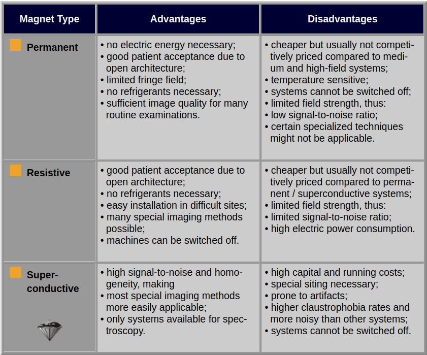
Table 03-02:
Properties of different magnet types.
Magnetic resonance imaging equipment can be combined with positron emission tomography (PET) into one machine [⇒ Shao 1997]. Do not confuse hybrid magnets with hybrid PET-MRI systems.
Hybrid PET-MRI systems can deliver complementary functional and anatomical information about a specific organ or body system down to the cellular, perhaps to the molecular level. At the time being, PET-MRI systems are research-focused work in progress [⇒ Bashir 2015].
The technical demands on such a hybrid systems are high, in particular arranging PET and MRI detectors into a single gantry. A detailed description has been published by ⇒ Jung 2016.


|
Chapter 3 — Page 2 |

|
|---|