


![]() n diagnostic imaging, the contents depicted on an image should reflect the essence of the original information as objectively as possible. However, there are limitations, as we have seen earlier: for instance, hardware and software of the MR equipment and possibly other outside forces influence image content (Figure 09-01).
n diagnostic imaging, the contents depicted on an image should reflect the essence of the original information as objectively as possible. However, there are limitations, as we have seen earlier: for instance, hardware and software of the MR equipment and possibly other outside forces influence image content (Figure 09-01).

Figure 09-01:
Object and ‘mirror’ image — excitation, in this case with a broom, will change picture elements soon.
In computerized imaging, be it nuclear medicine imaging, x-ray CT or angiography, or magnetic resonance imaging, pictures are composed of elements, called picture elements or pixels, which, in turn, reflect the content of volume elements or voxels.
Note, that this does not hold for conventional or digital radiography; here you get a shadowgram — it is not a tomographic or three-dimensional technology.
In principle, voxels could be as small as a single cell. In reality, however, voxel size depends on a number of limiting factors, with computer capacity and the signal obtained from an individual voxel being the main obstacles.
Therefore, for instance, 256×256×1 voxels are created of a slice of an object and turned into pixels. These 256×256 picture elements are called the image matrix. Figure 09-02 explains this.
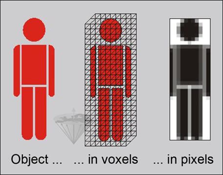
Figure 09-02:
Voxel and pixel. We want to image an entire person who for this purpose is mathematically divided into volume elements. In each voxel, the signals are averaged and turned into a number which represents a certain level on a gray scale. These numbers are then used to create a picture consisting of pixels.
The image matrix is characterized by the number of pixels in the x- and y-directions. It is defined by the steepness of the x-gradient (the frequency-encoding gradient) and the number of phase-encoding steps in the y-gradient. Both combined represent the field-of-view (FOV), as shown in Figure 09-03.
If the FOV is the whole head with an edge length of 25.6 cm and a matrix size of 256×256 is used, then a single pixel represents 1 mm. If the FOV is smaller (e.g., 12.8 cm) and the same matrix size is used, the spatial resolution is 0.5 mm.
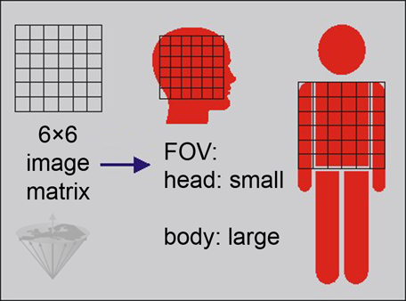
Figure 09-03:
Image matrix and field-of-view. In this case, we have an image matrix of 6×6, i.e., a grid of 6 rows and 6 columns with a total number of 36 pixels. Usually in MR imaging, the field-of-view is at least 256×256. Commonly, individual voxels and pixels are larger in body imaging than in head imaging.
As in other digitized imaging methods, voxel and pixel size influence spatial resolution and thus contrast. All anatomical structures within one voxel add to its averaged signal intensity in the final image. If the voxel has a large volume, it can contain many different structures and tissue types. In the final image pixel, they will be indistinguishable. If the voxel can be kept smaller, less structures will be represented by one single pixel, and therefore spatial resolution and, possibly, contrast will be better.
Data acquisition and reconstruction methods define different voxel shapes.
Isotropic reconstructions use cubes, while in anisotropic methods one side is longer than the two others. Although they may look the same in the picture plane, the content and thus the calculated number for the gray level representation in the pixel can be different (Figure 09-04).
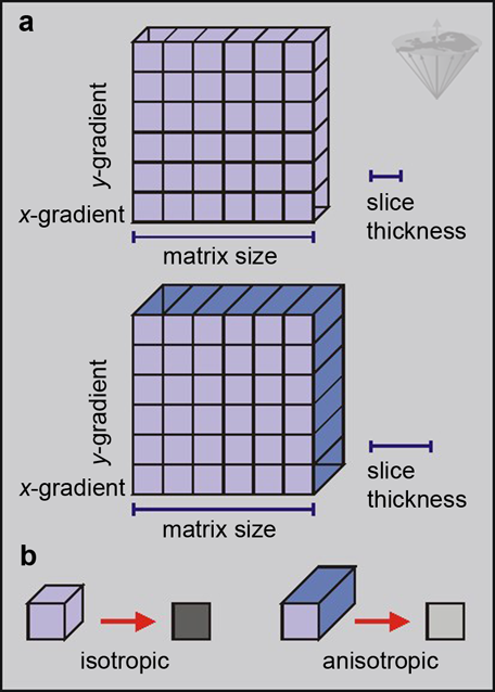
Figure 09-04:
Different slice thickness (a) can lead to isotropic or anisotropic volume elements (b) and different signal intensities.
The sometimes blurry features of these images are caused by the averaging of different structures. This is known as partial volume effect. The smaller the pixel size, the better will be the suppression of partial volume effects (Figure 09-05).
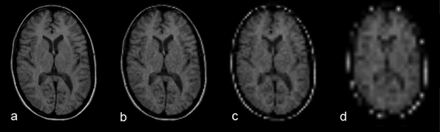
Figure 09-05:
Spatial resolution and partial volume effects: matrix size (a) 256×256, (b) 128×128, (c) 64×64, and (d) 32×32. Due to the partial volume effects, anatomic details disappear.
Simulation software: MR Image Expert®
However, the bigger the voxel size, the better will be the signal (and signal-to- noise). In general, the signal-to-noise is the determining factor for the final voxel-versus-pixel size.
Increasing the matrix size from 128×128 to 256×256, while keeping field-of-view, slice thickness and imaging constant, will reduce the signal-to-noise ratio by a factor of 4. Thus, the signal-to-noise has to be high enough to permit the increase in resolution.


|

|
|---|