


 s mentioned earlier, the initial high power excitation of the nuclei is accomplished with a short lasting RF pulse at a frequency close to or at the Larmor frequency. Both the radio waves and pulses are generated in the transmitter section of the magnetic resonance equipment.
The desired frequency is produced by a frequency synthesizer. The synthesizer output is then modulated with an 'envelope' to provide the required pulse shape for the RF excitation.
The receiver is basically a highly sensitive low-noise detector of signals in the high- and very-high-frequency (HF and VHF) range. The MR signals are typically a few microvolts in amplitude. In the receiver, the signal is improved by a factor of 500 to 1000. After this stage, the signal is converted from an HF resonance signal (MHz) to an audio frequency signal (kHz).
We refer to volume transmitter and receiver coils as regular coils.
The object to be studied, whether it is a one mm³ sample for chemical analysis or a whole human body, is placed inside such a coil or antenna. It should fill the coil as much as possible — the coil should have a good filling factor (> 70%).
The filling factor goes hand in hand with the quality factor (Q): the Q of a coil will depend on whether it is unloaded (no patient) or loaded (patient).
In many instances the coil Q is the dominating factor of the entire connected circuit. Q influences the signal-to-noise ratio, because the detected signal increases proportionally to Q while the noise is proportional to the square root of Q.
 The oscillating magnetic field B₁ of the RF coil has to be perpendicular to the main magnetic field B₀ generated by the magnet if the spins are to be excited.
The most common configuration is to have the main field orientated along the magnet bore, so the coil must produce a field perpendicular to the magnet bore (Figure 03-11).
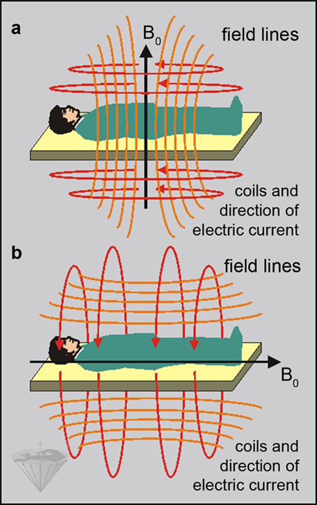
Figure 03-11:
The direction of the main magnetic field (B₀) depends on the orientation of the coils of the magnet.
The field can either be vertical as in (a) or horizontal as in (b). In superconducting and some resistive systems, the field is usually horizontal and thus parallel to the patient in the magnet.
Coils consist of one or more windings of low-resistance wire, usually copper. The geometry of the single or multiple windings is crucial for the proper excitation and subsequent signal detection.
Separate coils can be used for transmitting and receiving, but in most cases a single coil is used for both excitation and detection (transceiver coil).
Since the excitation pulse is many orders of magnitude stronger than the responding magnetic resonance signal emitted by the human body, the receiver will be damaged if it is subjected to all or part of the RF pulse. To overcome this problem, a device known as a transmit/receive switch is used which can very rapidly switch the routing of signals.
Coils come in different categories and for different magnet types. Some of the most popular coil geometries are the solenoid, saddle-shape (Helmholtz), birdcage, and slotted resonator.
This group of coils is identified as volume coils. Since a solenoid coil generates an oscillating magnetic field parallel to the coil's axis it has to be aligned across the bore of the magnet.
This limits the use of this kind of coil to magnetic fields that are orientated perpendicularly to the patient couch.
Figure 03-12 illustrates the form of some commonly used coils in MR imaging. Typical examples are head and body coils, or coils for studying the knees or the neck.
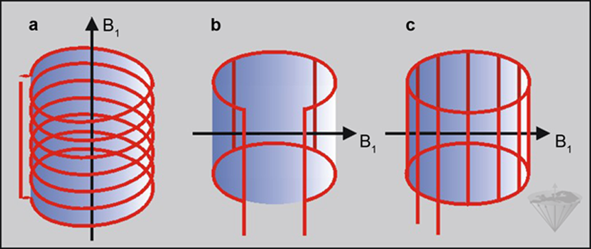
Figure 03-12:
Three different types of coils: (a) solenoidal coil; (b) Helmholtz or saddle-shape coil; (c) birdcage coil. Their oscillating magnetic field (B₁) must be perpendicular to the main magnetic field (B₀). Their RF field is uniform within the volume.
With the exception of surface coils all coils are designed to produce a very homogeneous RF field such that all of the sample experiences the same degree of excitation. Surface coils have a much higher sensitivity than homogeneous volume coils.
They are used to detect magnetic resonance signals from a small region close to the coil when it is placed, for instance, on a patient's spine, orbit, or temporo-mandibular joint. The advantage of using surface coils is that in the small volume of tissue close to the coil, one can obtain a better signal-to-noise ratio than that obtained by a standard volume RF coil.
However, surface coils receive a high signal only from an approximately hemispherical area below the coil with a depth of half its diameter (Figure 03-13).
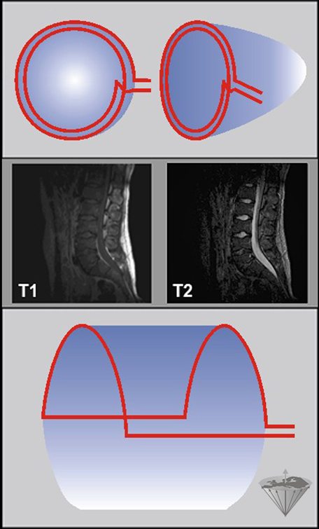
Figure 03-13:
Surface coils.
Top: Diagram of a simple surface coil. Since the intensity of the RF field varies with depth, the pulse angle will also vary with depth unless special ('adiabatic') pulses are used. Similarly, the detection sensitivity will also decrease with increasing depth.
Center: T1- and T2-weighted images of surface coil acquisitions of the lumbar spine. Spinal cord and spine are well depicted, but there is hardly any signal from the anterior parts of the pelvis.
Bottom: Wrap-around or half saddle-shape surface coil.
Thus, both the RF fields and the detection sensitivity of a surface coil are highly inhomogeneous, leading to a position-dependent excitation.
The variation of RF intensity with depth causes the flip angle to vary with depth when the surface coil is used as a transmitter. This problem can be overcome either by using special RF pulses or by transmitting the RF pulse on the standard body coil and only detecting the signal with the surface coil.
An increasingly common modification to the standard coil design is the quadrature coil (or circularly polarized coil) which uses at least two RF fields orthogonally to each other and improves both the efficiency of the coil and the SNR (signal-to-noise ratio) of the resulting signal by √2.
A phased array is a group of antennas in which the relative phases of the respective signals feeding the antennas are varied in such a way that the effective radiation pattern of the array is reinforced in a desired direction and suppressed in undesired directions.
In MR imaging, phased-array coils (or synergy coils) consist of a number of small surface coils [⇒ Roemer 1990]. The signals received by these coils can be collected simultaneously and the data can be combined to construct a single image of the body region covered.
Compared to a large surface coil with poor SNR, phased-array coils have the advantage of better signal-to-noise (Figure 03-14). However, each single subunit requires its own receiver channel, which makes image reconstruction difficult and coils expensive. Still, they had a major impact upon MR imaging and opened the way for parallel acquisition techniques combining the signals of several coils to reconstruct an image.
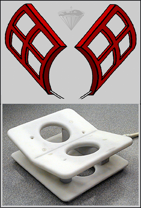
Figure 03-14:
Top: Phased-array coils, sketch. Four surface coils each left and right have been placed in an array with overlapping sensitivity volumes.
Bottom: Phased-array transceiver coil for breast imaging.
The analog signal emanating from the spins must be converted into a digital (numerical) form suitable for storing and processing on a computer. This digitization of the signal is achieved by using an analog-to-digital converter (ADC). The output of the ADC is a digital version of the FID for each data point. Afterwards the digitized FID is stored on the computer or another storage medium.
A specialized computer (the image processor) is used to pre-process and process the raw data into images. The Fourier transform of the raw data can be greatly accelerated by array processors or dedicated hardware.
The host computer is responsible for controlling and monitoring the entire MR system. Additional consoles can be connected to the host computer for such functions as patient management, display of image data and calculation results, image post-processing, and documentation and archiving.


|
Chapter 3 — Page 5 |

|
|---|