


 ne of the biggest challenges for MR imaging is the heart [⇒ Lanzer 1985] It not only contracts, it also moves due to respiration; it contains flowing blood, and its axes are not orthogonal to the rest of the body (Figure 14-23).
The latter point is not a restriction in MR imaging because it is basically a three-dimensional technique; the former points limited cardiac MR imaging strongly, because it used to be a slow modality and the time resolution required for cardiac imaging is less than 50 ms. Thus, cardiac imaging needs synchronization of data acquisition and the different kinds of motion of the heart, otherwise images are degraded.
 An in-depth overview of MR imaging of the heart and vessels was published by Lombardi and collaborators [⇒ Lombardi 2018].
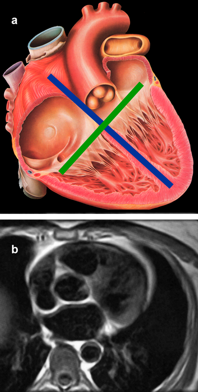
Figure 14-23:
(a) Anatomic sketch of the human heart with depiction of the long axis (blue) and the short axis (green).
(b)) Heart morphology: Transverse cut through the heart at the level of the aortic valve (black blood images).
Three types of synchronization are possible:
 Gating;
triggering;
slice following.
Gating;
triggering;
slice following.
Gating means opening a gate or a time window during which the data acquisition can run freely. The acquisition is stopped when the gate is closed, and continued as the gate opens again. The time window during which the gate is open is not necessarily the same from gate to gate.
Opening and closing of the gate is controlled by a physiological monitor, such as a chest elevation monitor for respiratory gating.
Triggering means receiving a signal that starts one or several pulses. The number of pulses is the same every time. For good timing, the trigger pulse should stem from an easily definable and exact physiological incident, like the peak of the R-wave in the QRS-complex of an electrocardiogram. Distortions of the detected QRS-complex are readily introduced by gradient pulsing or by material in ECG electrodes. Some problems cannot usually be avoided, such as the elevation of the T-wave due to the flow of blood through a magnetic field (see Chapter 18).
This effect increases with field strength and with dobutamine stimulation of the heart in stress examinations.
Since the elevation of the T-wave can give falsely detected R-waves, the triggering parameter should be set well ahead of the QRS-complex. There are some advanced ECG systems that use an out-of-magnet recorded vector ECG as a mask to get an undisturbed ECG inside the magnet during imaging.
Slice following is a technique where both the movement of the diaphragm during respiration and the heart during contraction is monitored by the system. Through checking the positions of anatomical landmarks immediately before and after the acquisition of an imaging profile, the displacement of the acquired profile can be checked (and discarded if outside given borders) and the displacement of the following profile can be predicted. Slice following is often used in combination with triggering to achieve better temporal resolution.
Measurement of myocardial wall motion is possible by myocardial tagging. Tagging entails labeling a strip in the myocardium by magnetic saturation. The spins of the dark mesh in Figure 14-24 were selectively excited; they retain a state of excitation different from their neighbors for the duration of T1 and wall motion can be followed [⇒ Zerhouni 1988].
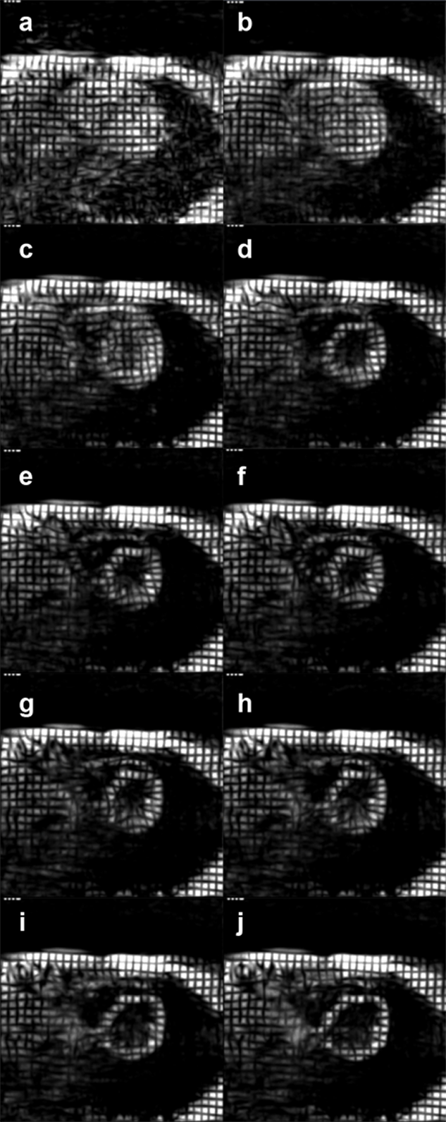
Figure 14-24:
Heart examination with spin tagging.

Figure 14-24-Video:
Heart examination with spin tagging. Myocardial wall motion can be followed because the spins of the dark mesh were selectively excited. They retain a state of excitation different from their neighbors for the duration of T1.
For the depiction of cardiac and great vessel morphology, static studies in several phases of the heart cycle can be performed, usually as RSE or GRE studies, primarily as black blood images. They should be performed as a multi-slice, multi-phase, double-oblique angulated acquisition, where special attention must be paid to the patient’s heart frequency.
Care should be taken about the chosen imaging planes; four-chamber views are generally coronal, but long-axis views can be either sagittal or transverse, whereas short-axis views can be either transverse or sagittal.
Bulk flow either from shunts across the septum, regurgitant jets through valves closing insufficiently, or just through lumina and vessels can be visualized by gradient-echo techniques.
These studies must have reasonable temporal resolution to describe the different phases of the heart cycle, typically 16 or more, depending on the clinical question (Figure 14-25). The results will yield an image with muscular tissue in gray, static liquid in white and high-velocity jets in black (signal void). Consequently, both ordinary flow and regurgitant jets are seen, but cannot be quantified immediately. One quantification method being employed is to measure the area (or volume) of the regurgitant jet (signal void) and compare it to the area (or volume) of the chamber.
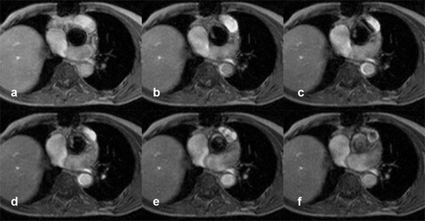
Figure 14-25:
Patient with several transient ischemic attacks. Gradient-echo images four millimeters above the aortic valve during different phases of the cardiac cycle show a pendulating thrombus.

Figure 14-25-Video:
Patient with several transient ischemic attacks — movie.
Another technique tracks the signal intensity of the blood in the chamber during the cardiac cycle. The total signal intensity increases in normal patients during systole, but decreases markedly in patients with regurgitation. The percentage of decrease is found to be dependent on the severity of the regurgitation.
Angiographic techniques such as flow quantification can also be utilized and then net flow through an orifice can be accurately quantified.
To date, combinations of RSE/GRE (CE-FLASH) pulse sequences have been found to be the most efficient method to image the heart by magnetic resonance. The goal of such an examination is to combine the evaluation of morphology with functional features. In clinical routine, imaging time should not exceed thirty minutes; image processing, and particularly interpretation, will take longer. Great care has to be put into planning and optimizing a heart examination, and certain trade-offs should be realized.
1.5T systems are the preferred equipment for cardiac imaging. ultrahigh machines (3 T and above) are prone to destructive artifacts and are limited in their applications because of specific absorption rate (SAR) restrictions. They might be used for first pass contrast-enhanced perfusion imaging, tagging sequences, and dynamic 3D flow imaging.
In rapid spin-echo images, regional abnormal wall motion or abnormal wall thickness is seen, as well as pericardial disturbances. Fatty deposits in the myocardium of the right ventricle and intra- or extracardiac tumors, together with crypts and ducts, are also generally found with ease.
Gradient-echo images tend to give somewhat poorer edge description of the endocardium, but a good overview of different hypertrophies. Specially designed gradient-echo sequences like True FISP and Balanced FFE do, however, give excellent blood-tissue contrast.
Furthermore, both restricted and dilated cavities, insufficient valves and tracts are easily seen. The general flow pattern and the total overview of the heart add to the general understanding of cardiac performance.
A good and detailed textbook was published by Manning and Pennell in 2010 [⇒ Manning 2010]; helpful clinical guidelines are given by a team of several cardiac imaging societies [⇒ Kramer 2013].
Both first-pass contrast uptake and late-enhancement imaging are gaining ground in cardiac diagnostic imaging. These kinds of contrast studies are used to evaluate cardiac perfusion and perfusion reserve and to qualify the possible viability of cardiac tissue. Coronary artery imaging is also progressing using multiple different 2D- and 3D-imaging sequences (RSE, rapid GRE, SE-EPI, rapid GRE-EPI).
The resolution reached has been good enough to persistently describe 7-10 cm of the main coronary arteries (RAD, LAD, and circumflex), but not the collaterals. This resolution is sufficient to evaluate the patency of grafts and MR coronary artery imaging can be used in patients with severe anaphylactic reactions to contrast media, but it is still not a sufficiently robust screening tool (Figure 14-26).
Cardiac MR imaging is considered the method-of-choice for examinations of congenital heart disease, acquired diseases of the great vessels and tumors infiltrating or close to the heart and valuable in a number of other clinical areas such as cardiomyopathies, pericardial diseases and post-transplantation examinations.
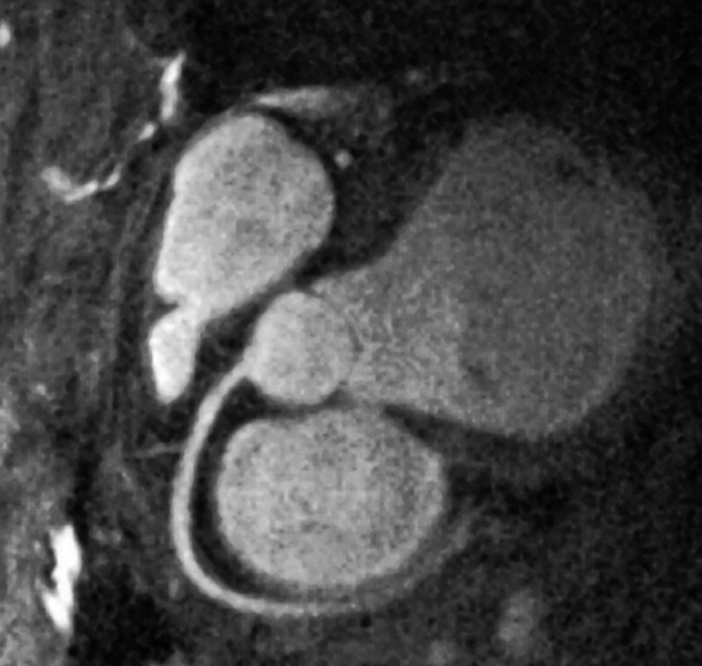
Figure 14-26:
Depiction of the coronary arteries without contrast agent application by spiral 3D rapid gradient-echo using navigator techniques and diastolic gating.


|

|
|---|