


 he main magnetic field (or more precisely, the lines of magnetic flux) can be distorted by a number of factors outside the MR imaging suite, for instance by large stationary or moving ferrometallic objects such as elevators or passing vehicles.
The field has to be protected by shimming or shielding, which is generally performed properly by the manufacturer of the MR equipment during installation. Therefore, field inhomogeneities from the outside are at present seldom responsible for image artifacts.
Any local internal distortion of the magnetic field cannot be corrected by shimming.
The most common causes of such local distortions are the presence of ferromagnetic foreign bodies and susceptibility effects. Ferromagnetic objects usually cause an area of total signal loss around the object and distort the signal intensity at the edge of this region (Figure 17-04 and Figure 13-19).
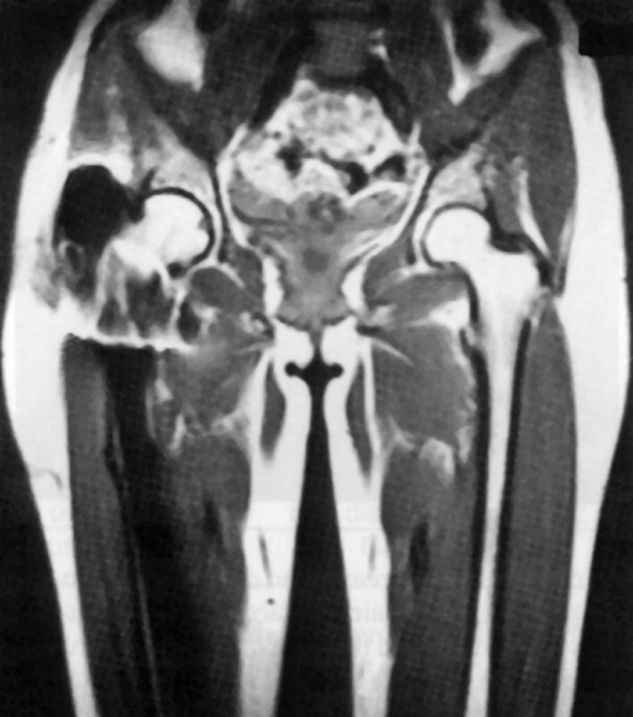
Figure 17-04:
Artifacts resulting from the presence of ferromagnetic material. Signal loss and signal distortion associated with a ferromagnetic prosthesis in the right leg.
For this reason, all external metallic objects such as jewelry (including piercings), watches (and guns — no joke) must be removed from the patient and accompaning persons. A change of clothing is advised to avoid problems with metallic zippers and other like devices.
Any implanted ferromagnetic material obviously has to be tolerated, but gradient echo scans should be avoided in such cases since they are affected to a greater extent than spin echoes.
Owing to their conductive properties, some nonferrous metal implants can disturb the magnetic field by low-level eddy currents.
Artifacts can also be caused by the ferromagnetic pigments used in eye and other makeup (e.g., mascara) and tattoos. This can result in a significantly reduced image quality, particularly in the case of studies of the orbit.
The susceptibility of a tissue tells us how easily it can be magnetized. The susceptibility values for most tissues fall within a fairly narrow range.
However, the presence of ferromagnetic material (e.g., iron deposition in tissues, localized high concentration of hemoglobin after a hemorrhage, or high concentration of ferromagnetic contrast agents) or tissue-air interfaces lead to local variations in the susceptibility which result in a reduction of the quality of the local field (Figure 17-05).
At high and ultrahigh fields susceptibility artifacts can become a major problem. Air-tissue interfaces and iron deposits in tissues can distort or erase the signal, in the brain for instance in the frontal lobe, the posterior fossa, and auditory cortex.
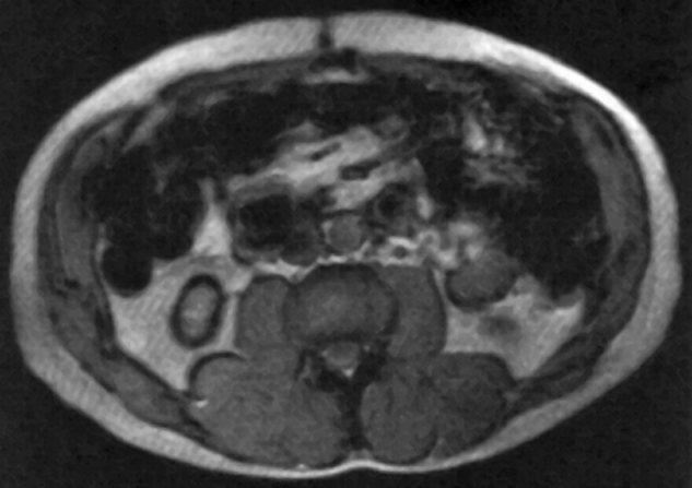
Figure 17-05:
Susceptibility artifacts created by ingested ferromagnetic particles used as an oral contrast agent. Because the concentration of the particles is too high, the local magnetic field is disturbed and image artifacts are created.
 The form of the susceptibility artifact depends on the local conditions, and both increases and decreases in signal intensity are possible. Tissue-air interfaces which give rise to such artifacts can be found in the lungs, around the sinuses and in the nasopharynx. The lack of signal from the lungs is caused by the air in the lungs and the susceptibility artifacts produced by the interfaces between air and lung tissue.
The distortions increase with field strengths and can become a nuisance at high and ultrahigh fields [⇒ Farahani 1990].
The effect of obtrusive susceptibility artifacts is reduced by using spin-echo sequences rather than gradient-echo sequences. The presence of local field variations can be determined by using either a phase image or a special pulse sequence which exploits the interaction between two echoes to produce a local field map.
In contrast-enhanced MR angiography contrast agents can induce susceptibility artifacts. If these artifacts are severe, they can be reduced by acquiring the full k-space; partial (asymmetric) echo sampling (and/or halfscan) should be reduced or avoided.


|

|
|---|